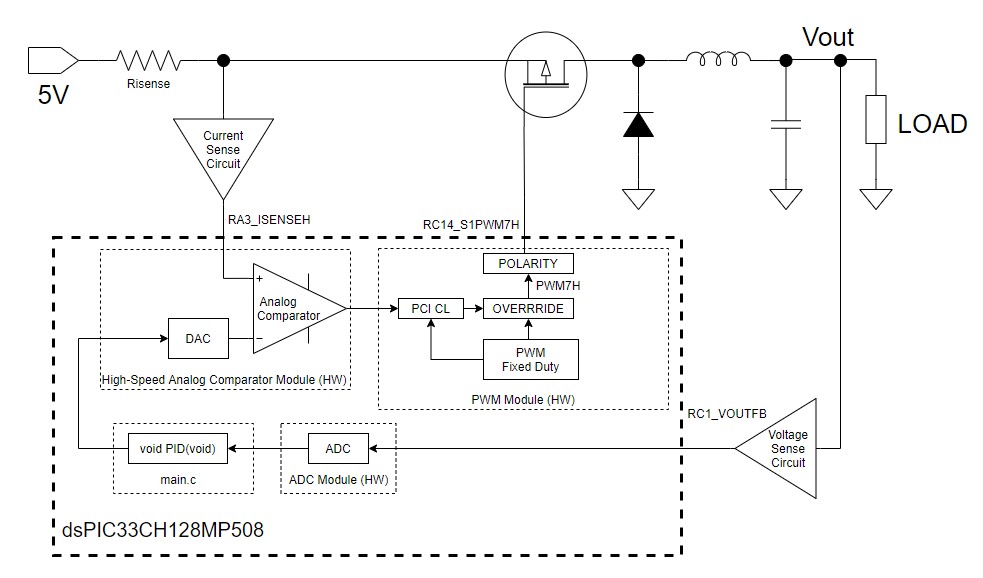
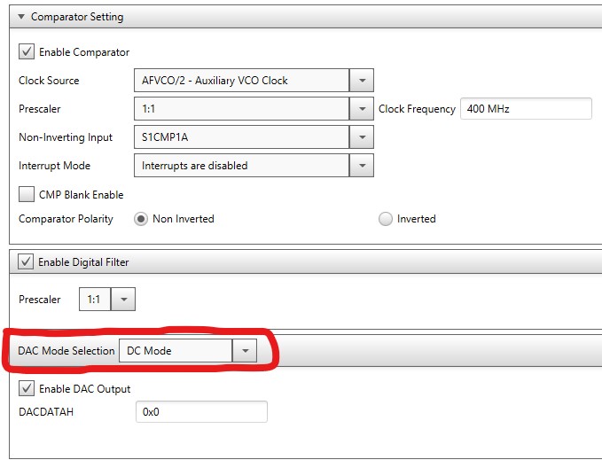
In the previous article Current Mode Converter , the PWM control is generated based from the comparison of the output of the DAC to the actual current of the high side mosfet. See illustration below. The DAC converts the digital result value of the PID function into analog. The DAC was configured in DC Mode as seen on the image below.
In the DC Mode, the output of the DAC changes only after the DACDATAH is updated.
Actually, the DAC has a slope compensation feature in which the output of the DAC ramps down after DACDATAH is updated. This method makes the control more stable. In this article I will configure the DAC from DC Mode to slope compensation mode.
PROCEDURE
Open the master and slave projects of the current mode buck control in MPLAB IDE. The MPLAB code of the buck control project is stored here: buck_ictrl.zip
Right click on the master project and make it the main project.
Connect the DM330028 board to the PC. Click the "Make and Program" button on MPLAB to program the code to the dsPIC33 IC. Wait until a "Programming/Verify complete" message is prompted in the output window of MPLAB.
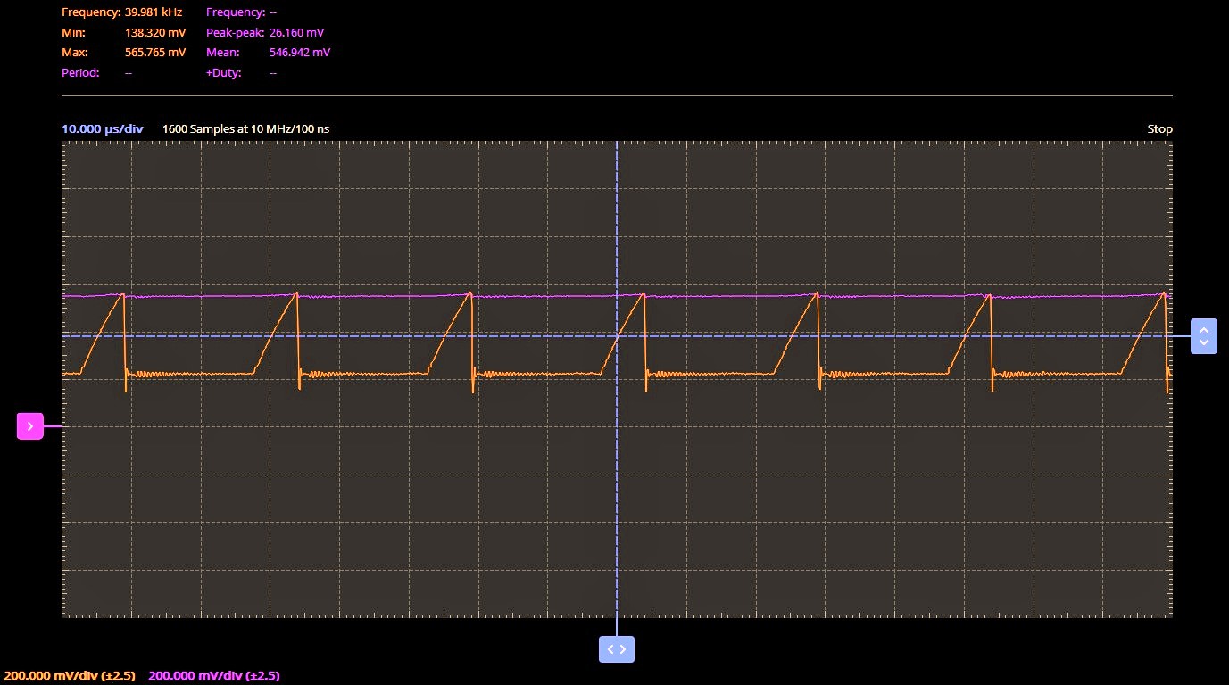
If we connect an oscilloscope to RB2 and RA3, we would see the waveform below. We can see that the orange waveform (RA3) shuts off after reaching the purple waveform (RB2). The RB2 is the DC value output from the DAC and RA3 is the current sense signal that is fed to the comparator. Note: RB2 is not shown in the simplified schematic that is illustrated above.
Right click on the slave project and make it the main project.
Click MCC button and wait until the slave MCC is completely loaded.
After the MCC is loaded, open the Master Core Configuration.
In the Master Core Configuration window, click "Load Slave Settings from Master Configuration" button. Select the master_config.mc3 file in the master.X folder then click Open button. Wait until the Notifications [MCC] window is updated.
In the Project Resources window, click CMP1 (Don't click X) to open the CMP1 analog comparator window. Wait until the window is completely loaded.
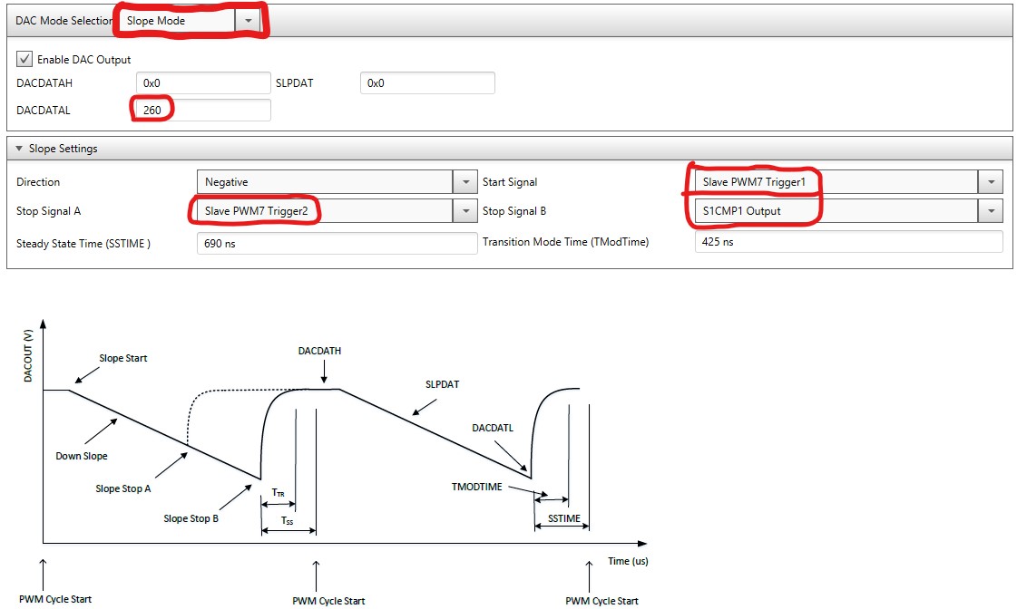
Configure the DAC as shown below. I made the lowest value DACDATAL as 260 because this is 0 current offset value of the DM330028 current sense amplifier. In this configuration, the DAC output will start to ramp down after Slave PWM7 Trigger 1 and ramps back up after either Slave PWM7 Trigger2 or S1CMP1 Output is triggered.
In the Project Resources window, click PWM (Don't click X) to open the PWM window. Wait until the window is completely loaded.
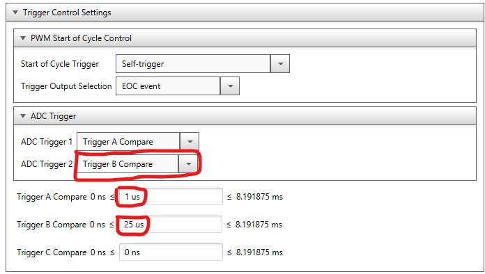
Expand the Trigger Control Settings and configure it as shown below. Trigger 1 is triggered 1us after the start of PWM cycle. We have now configure the DAC output to start ramping down after 1us after the start of PWM cycle. Trigger 2 is triggered 25us after the start of PWM cycle. 25us is the period of the 40kHz PWM so the DAC output will go back to DACDATH at the end of the PWM cycle.
Click the Generate button. Click yes button in the confirmation dialog box and wait until Generation complete is prompted in the MCC output window.
Click MCC toolbar button to close the MCC configurator application.
In the projects pane, open main.c file of the slave project.
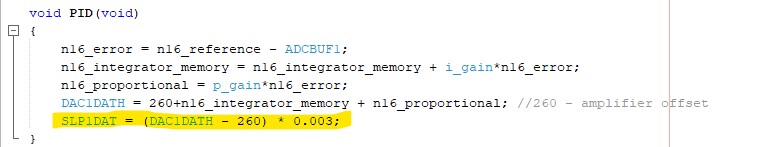
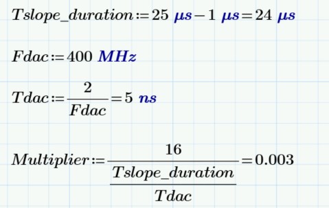
In the PID function, add the highlighted code as shown below. 260 is the assigned value of the DAC1DATL. The multiplier 0.003 calculation is shown below.
Right click on the master project file and set it as the main project.
Click Make and Program button and wait until the Programming/Verify complete is prompted on the log window.
RESULT
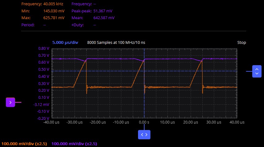
Purple waveform - DAC output Orange waveform - MOSFET current sense amplifier output
It can now be seen that the DAC output (purple) ramps down 1us after the MOSFET begins to conduct (orange waveform) and then quickly return back to high value after the MOSFET has turned off.

Comments