Simulation of Buck Converter using discrete PID in LTSPICE

If you are in a hurry and want to immediately verify the simulation, download and unzipped the file below then run the buck.asc file in LTSPICE:
Introduction
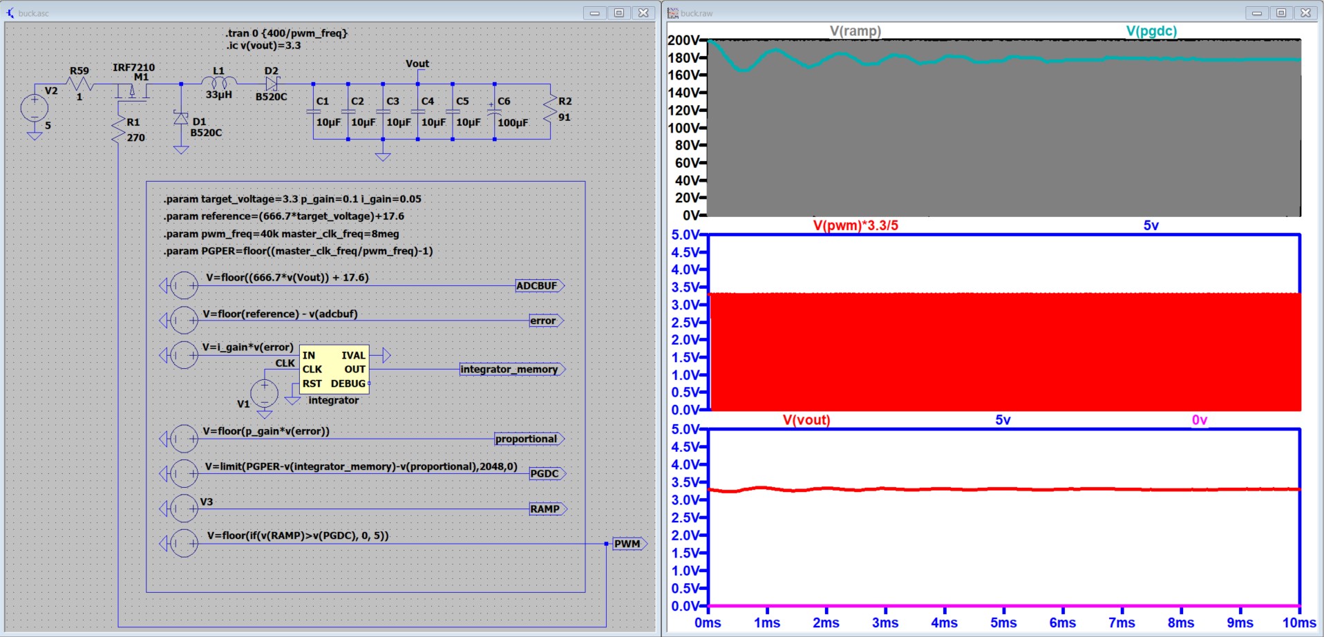
This article presents a LTSPICE simulation of a PWM buck converter controlled by a discrete PID. The simulation result will be compared to the result of the actual implementation of a digitally controlled buck converter (Buck converter). Below table is a comparison of the source code from the the actual implementation (DSPIC33 IC) and the components used in this LTSPICE simulation.
| MPLAB (DSPIC33) Source Code | LTSPICE component / parameter |
PARAMETERS #define target_voltage 3.3 | PARAMETERS .param target_voltage=3.3 p_gain=0.1 i_gain=0.05 |
ANALOG TO DIGITAL CONVERSION (use the default configuration of ADC) | ANALOG TO DISCRETE CONVERSION  |
ERROR CALCULATION n16_error = n16_reference - ADCBUF1; | ERROR CALCULATION  |
INTEGRATION n16_integrator_memory = n16_integrator_memory + | INTEGRATION 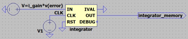 |
PROPORTIONAL n16_proportional = p_gain*n16_error; | PROPORTIONAL  |
DUTY CYCLE PG7DC = PG7PER - n16_integrator_memory | DUTY CYCLE  |
PWM GENERATION Configured in MCC PWM7, pwm freq=40kHz, | PWM GENERATION 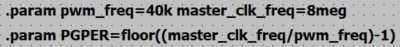 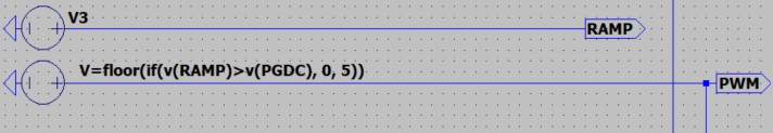 |
Note: I used the floor() function in LTSPICE to convert the values into discrete.
Result
Below is the resulting waveform from 9.68ms to 10ms of the simulation. We can see that the on time width measured is 3.34ms which is only 16.5% duty cycle.
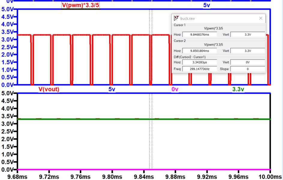
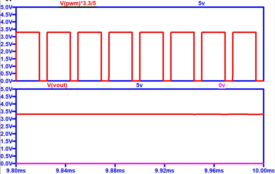
In the actual implementation, the duty cycle measured by the oscilloscope was 20%. Most likely cause why the actual implementation has higher duty cycle is that the MOSFET used in the actual implementation has a higher turn on resistance (BSS308PE Rdson=130mΩ@4.5V). The MOSFET (IRF7210) I used in the LTSPICE simulation has a Rdson of only 5mΩ. I changed the MOSFET to part number FDC5614P which has a Rdson value of 105mΩ and run the simulation again, the result below is now similar to the actual implementation.
Conclusion
It was demonstrated that discrete control of PWM can be simulated in LTSPICE that can generate similar result with an actual implementation. It is better if we use the right part model. For example, the Rdson has a significant impact on the duty cycle.
Comments