This is a continuation of tutorial Potentiometer. In this tutorial, we will determine the Back EMF (BEMF) level that we need to detect. The BEMF detection is the key to determine the optimum commutation speed of the motor. Below are the map of the BEMF signals of the X-NUCLEO-IHM07M1 board.
Signal Name
Definition
Header Pin
MCU Pin
GPIO_BEMF
This pin should be pulled down to
enable BEMF measurement.
C10_1
PC9
BEMF1
Phase 1 Back-EMF signal
C7_37
PC3
BEMF2
Phase 2 Back-EMF signal
C7_34
PB0
BEMF3
Phase 3 Back-EMF signal
C10_15
PA7
We will use BEMF3 as the BEMF detector because this pin can be connected to the positive input of an internal analog comparator of the MCU. A DAC will be used as negative input of the comparator. The DAC level will be determined using trial and error.
Configuration
Open the Six_Step project on STM32CubeIDE. This is the project generated on the 2nd tutorial Potentiometer.
Open the Six_Step.ioc.
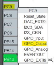
On the Pinout view, click on PC9 and select GPIO_Output. This pin will be used to enable the BEMF measurement.
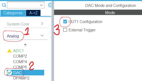
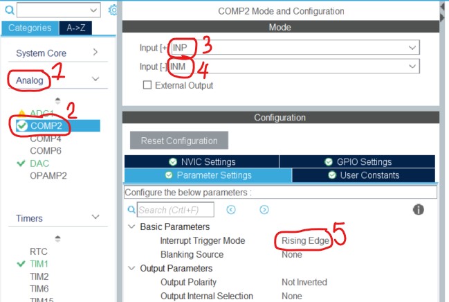
Click Analog->DAC. Enable the OUT1 Configuration.
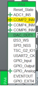
On the Pinout view. Click PA4 and select COMP2_INM.
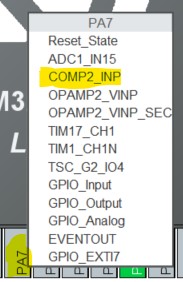
On the Pinout view. Click PA7 and select COMP2_INP.
Click Analog->COMP2. Select INP as positive input. Select INM as negative input. In the Parameter Settings, select Rising Edge as the Interrupt Trigger Mode.
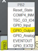
On the Pinout view, click PB2 and select GPIO_Output. This pin is connected to a LED. We will turn on the LED everytime the comparator 2 interrupt is triggered and turn off everytime the TIMER 16 interrupt is triggered.
Ctrl+s to save the configuration and go to main.c
Coding
In main.c /* Initialize all configured peripherals */. Make sure that the MX_DMA_Init(); is written first before MX_ADC1_Init();, else the DMA will not initialize properly.
After #define ADC_BUF_LEN 1, add #define BEMF_LIMIT 1 // Volt(s)
Before /* USER CODE END 2 */ add the following code: //BEMF DAC for comparator HAL_DAC_Start(&hdac, DAC_CHANNEL_1); DAC1->DHR12L1 = DAC1_DHR12L1;
//BEMF Comparator HAL_COMP_Start_IT(&hcomp2);
Next we add the comparator interrupt handler, add the following code before /* USER CODE END 4 */ line : void HAL_COMP_TriggerCallback(COMP_HandleTypeDef *hcomp) { if (hcomp == &hcomp2) HAL_GPIO_WritePin(GPIOB, GPIO_PIN_2, GPIO_PIN_SET); // Turn on LED }
Then reset the LED on the TIMER16 interrupt. Add HAL_GPIO_TogglePin(GPIOB, GPIO_PIN_2); // Turn off LED after the TIM16->CCR1 = (adc_buf[0] * TIM16_PERIOD) >> 12 ; line.
Determine Optimum BEMF
On the X-NUCLEO board. Set JP1 and JP2 to open position. Set JP5 and JP6 to 1Sh position.
Connect the 12V DC power supply to J1 and the motor to J2.
Connect an oscilloscope probe to C10_15. C10_15 is the BEMF3 signal.
Connect an oscilloscope probe to C10_22. C10_22 is the LED signal.
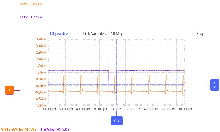
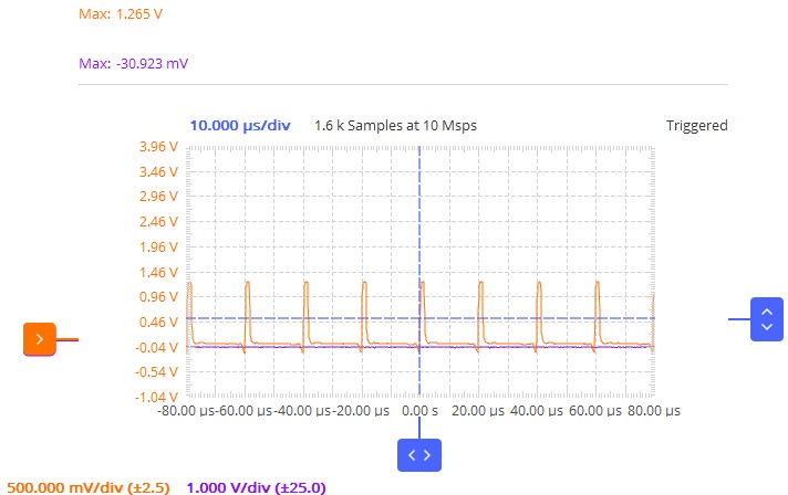
Click Run->Run menu to compile and load the program to the MCU. The orange waveform below is the BEMF of PH3. The purple waveform is the LED signal which is turned on every time BEMF rises and then turned off by TIMER16 which has a frequency of about 10kHz.
We can see that the peak voltage of the BEMF at zero torque position is 1.268V.
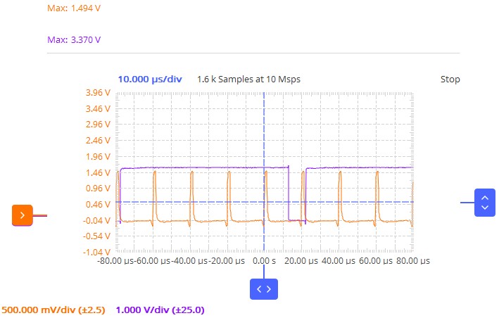
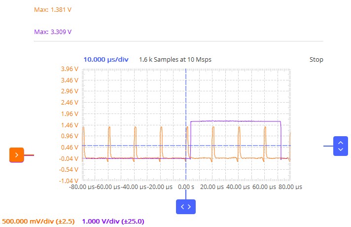
Now rotate counter clockwise the motor until you feel the maximum torque. It is important that the potentiometer is set to minimum position while doing this to easily rotate the motor. Below is the waveform at maximum torque that I got.
We can see that the peak voltage of the BEMF at maximum torque position is 1.494V.
Therefore to balance torque and speed, we will use 1.381V as the BEMF level for the comparator.
Change #define BEMF_LIMIT 1 // Volt(s) to #define BEMF_LIMIT 1.381 // Volt(s) Click Run->Run. We should observe now that the LED is not turning on at zero torque: But if we rotate counter clockwise the motor so that the peak voltage of the BEMF reaches 1.381V we will observe the LED begins to toggle.
Below is the video demo of the BEMF detection. Observe that the LED shines as I rotate the motor.

Comments