In this tutorial, we will configure and add code to utilize the potentiometer of the X-NUCLEO-IHM07M1 board in adjusting the current limit of the stator PWM. Below table summarizes the map of the potentiometer signal vs board connector pin and MCU pin. We will set PB1 of the MCU as an analog input. We will configure an ADC and DMA to automatically store the voltage level on PB1 to a memory.
Signal Name
Board Connector
MCU Pin
SPEED
C10_24
PB1
The TIMER16 that is used for current reference PWM will be configured to have its interrupt enabled. The interrupt will be used to change the value of the current reference based from the value stored in the memory that is being updated by the DMA.
CONFIGURATION
Open the Six_Step project on STM32CubeIDE. This is the project generated on the first tutorial Stator PWM.
Open the Six_Step.ioc.
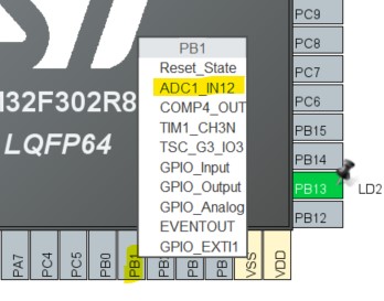
On the Pinout view, click on PB1 and select ADC1_IN12.
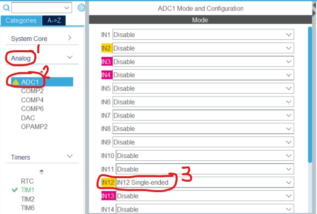
Click Analog->ADC1 and select IN12 Single-ended for IN12.
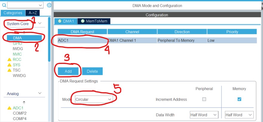
Click System Core->DMA. Configure as illustrated below.
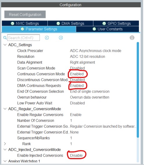
Go back to the ADC1. Configure as illustrated below.
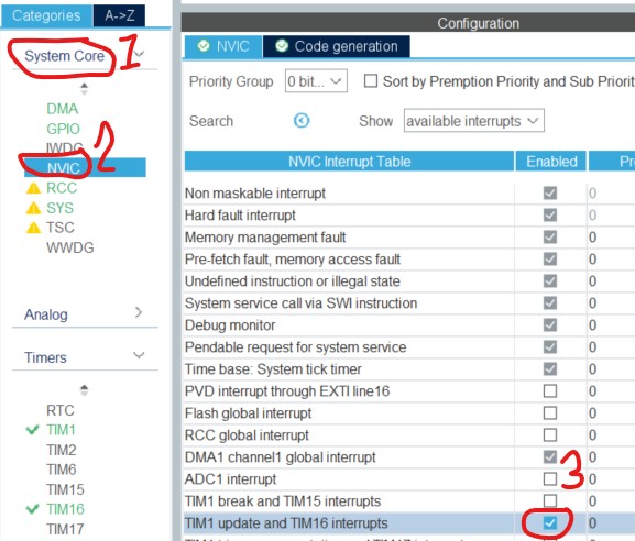
Click System Core->NVIC. Enable TIM1 update and TIM16 interrupts.
Ctrl+s to save the configuration and go back to main.c
CODING
In main.c /* Initialize all configured peripherals */, check if MX_DMA_Init(); is written first before MX_ADC1_Init();. The DMA must be initialized first before the ADC, else the DMA will not work.
Add uint16_t adc_buf[ADC_BUF_LEN]; after /* USER CODE BEGIN PV */ line.
After TIM16->CCR1 = TIM16_DUTY; line, add the following: //ADC for current reference limit HAL_ADC_Start_DMA(&hadc1, (uint32_t*) adc_buf, ADC_BUF_LEN);
Rename HAL_TIM_Base_Start(&htim16); to HAL_TIM_Base_Start_IT(&htim16);
Rename HAL_TIM_PWM_Start(&htim16, TIM_CHANNEL_1); to HAL_TIM_PWM_Start_IT(&htim16, TIM_CHANNEL_1);
After /* USER CODE BEGIN 4 */ add the following code: void HAL_TIM_PeriodElapsedCallback(TIM_HandleTypeDef *htim) { if(htim==&htim16) TIM16->CCR1 = (adc_buf[0] * TIM16_PERIOD) >> 12 ; }
TEST
On the X-NUCLEO board. Set JP1 and JP2 to open position. Set JP5 and JP6 to 1Sh position.
Connect the 12V DC power supply to J1 and the motor to J2.
Connect an oscilloscope probe to J16. J16 is the negative input reference of the built-in comparator of the driver IC.
Connect an oscilloscope probe to C7_36. C7_36 is the stator current feedback signal.
Connect an oscilloscope probe to C10_12. C10_12 is the output of the driver IC comparator.
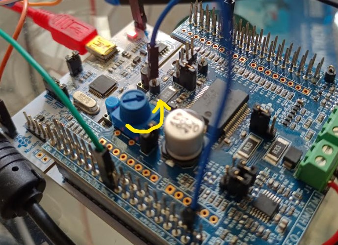
Make sure the potentiometer is set to minimum position as shown below:Caution: If potentiometer is set high, the driver IC may get too hot.
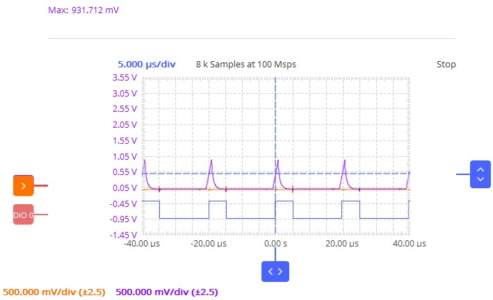
Click Run->Run menu to compile and load the program to the MCU. We should get a similar waveform on the oscilloscope below. The orange waveform is the current reference. The purple waveform is the current feedback. The blue waveform in the bottom is the output of the comparator.
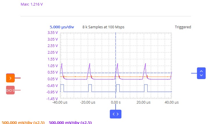
Rotate the potentiometer by about 45°. Observe that the peak of reference current and peak current increases as shown below. We can confirm now that the current limit of the stator can be adjusted by the potentiometer.

Comments