Sensorless 6-Step Control for 3-Phase Brushless Motor Tutorial - Part 1 Stator PWM

Introduction
This tutorial is done with NUCLEO-F302R8 MCU board with X-NUCLEO-IHM07M1 expansion board and BR2804-1700KV-1 3-phase motor. The IDE used is STM32CubeIDE 1.8.0.
Create Project
- Open STM32CubeIDE.
- File->New->STM32 Project.
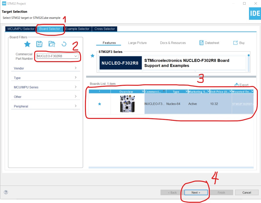
- After "STM32 Project" dialog is loaded. Click on "Board Selector" Tab. Type "NUCLEO-F302R8" as the part number. Click the board listed on the left then click Next button.
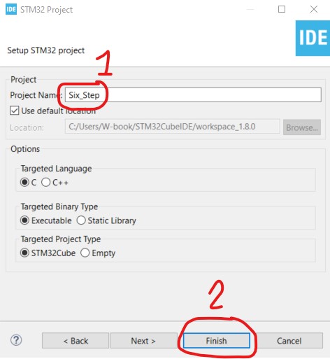
- Name the project "Six_Step" then click Finish button.
- If "Board Project Options" dialog box is displayed. Click "Yes" to initialize all peripherals with their default Mode.
Configure the Stator PWM
The X-NUCLEO-IHM07M1 expansion board uses L6230 DMOS driver IC. The EN1, IN1, EN2, IN2, EN3 and IN3 pins of the IC are used to control the MOSFETS of the IC. Below table is the definition and map of these pins to the board header pins and MCU pins.
| L6230 Pin | Definition | Board Header Pin | MCU Pin |
| EN1 | PH1 Enable | C7_1 | PC10 |
| IN1 | PH1 Hi/Low | C10_23 | PA8 |
| EN2 | PH2 Enable | C7_2 | PC11 |
| IN2 | PH2 Hi/Low | C10_21 | PA9 |
| EN3 | PH3 Enable | C7_3 | PC12 |
| IN3 | PH3 Hi/Low | C10_33 | PA10 |
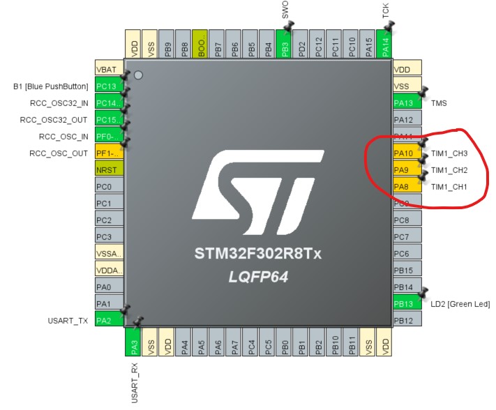
We will connect the MCU Pins PA8, PA9 and PA10 defined above as PWM output of the TIMER1.
- On the pinout window, click PA8 and select TIM1_CH1.
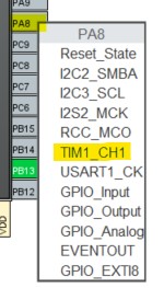
- Do the same thing to PA9 (TIM1_CH2) and PA10 (TIM1_CH3). The pinout setting should look like below.
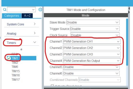
- Click Timers->TIM1 and configure the channels as shown below. Channel 4 will be used later in an interrupt.
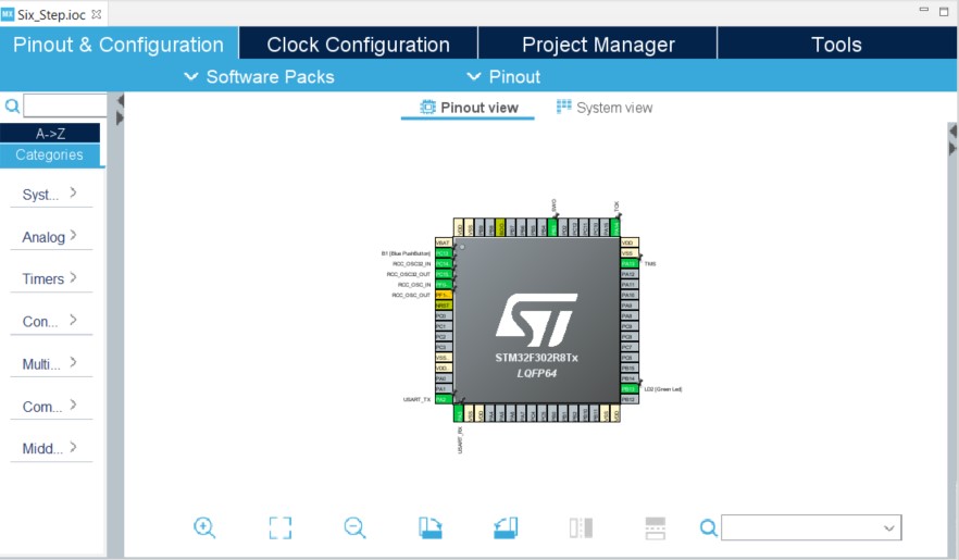
After the configuration, the PA8, PA9 and PA10 pins should turn green as shown below.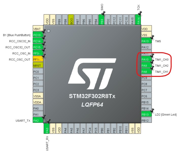
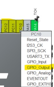
The MCU pins PC10, PC11 and PC12 that will be used to enable each phase of the L6230 DMOS driver IC need not be controlled by PWM. For each pin, set it as GPIO_Output.
Cycle by Cycle Duty Control
We will control the duty cycle of the Stator PWM by utilizing the current on the stator. The L6230 DMOS driver IC has a built-in analog comparator that we can utilize to clear the output of the Stator PWM for every Stator PWM cycle. Below table is the definition of the comparator pins and map of these pins to the board header pins and MCU pins.
| L6230 Pin | Definition | Board Header Pin | MCU Pin |
| CP+ | Stator Current Feedback | C7_36 | PC1 |
| CP- (Filtered) | Current Reference | J16 Ring (Filtered) C10_27 (PWM) | PB4 (Ref PWM Output) |
| CPOUT | Comparator Output | C10_12 | PA12 |
We'll use PA12 pin as input to the TIMER1 as clear pin so everytime the L6230 DMOS driver IC CPOUT turns high, the output of the PWM is cleared or reset.
- On the pinout view, click on PA12 pin and select TIM1_ETR. Then on the Mode window, Select ETR IO as Clearing Source.
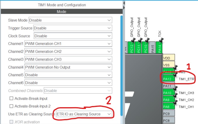
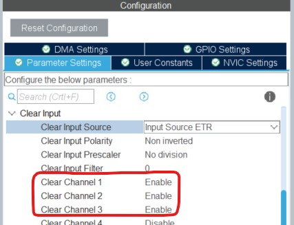
- On the Configuration, Enable Clear Channel 1, Clear Channel 2 and Clear Channel 3.
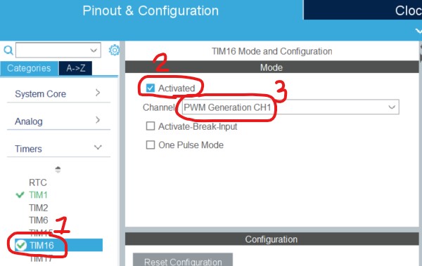
Next, we'll set the MCU pin PB4 as reference PWM to the comparator of the L6230 DMOS driver IC.
- On the pinout view, click PB4 and select TIM16_CH1.
- Click TIM16. Click Activated and select "PWM Generation CH1" as Channel1.
CODING
Save the configuration to generate all the initialization code.
- Ctrl+s to save. Wait until main.c file is generated and displayed.
- Insert the following definition codes after the /* USER CODE BEGIN PD */ line:
#define STATOR_PWM_FREQ 50E+3 // Hz#define CURRENT_IREF_LIMIT 0 // Ampere#define CURRENT_REF_PWM_FREQ 10E+3 // Hz#define R44 0.33 // Ω - sense resistor#define TIM1_PERIOD ((uint16_t)(64E+6/STATOR_PWM_FREQ - 1)) // calc good only if prescaler is 0#define TIM1_DEFAULT_DUTY ((uint16_t)(TIM1_PERIOD/2)) // limit stator duty to 0.5#define TIM16_PERIOD ((uint16_t)(64E+6/CURRENT_REF_PWM_FREQ - 1)) // calc good only if prescaler is 0#define CURRENT_VREF_LIMIT (CURRENT_IREF_LIMIT*R44) // volts#define TIM16_DUTY (TIM16_PERIOD*CURRENT_VREF_LIMIT/3.3) // current reference duty cycle#define PH1_HIGH TIM1->CCR1 = TIM1_DEFAULT_DUTY; HAL_GPIO_WritePin(GPIOC, GPIO_PIN_10, GPIO_PIN_SET);#define PH1_LOW TIM1->CCR1 = 0; HAL_GPIO_WritePin(GPIOC, GPIO_PIN_10, GPIO_PIN_SET);#define PH1_OFF HAL_GPIO_WritePin(GPIOC, GPIO_PIN_10, GPIO_PIN_RESET);#define PH2_HIGH TIM1->CCR2 = TIM1_DEFAULT_DUTY; HAL_GPIO_WritePin(GPIOC, GPIO_PIN_11, GPIO_PIN_SET);#define PH2_LOW TIM1->CCR2 = 0; HAL_GPIO_WritePin(GPIOC, GPIO_PIN_11, GPIO_PIN_SET);#define PH2_OFF HAL_GPIO_WritePin(GPIOC, GPIO_PIN_11, GPIO_PIN_RESET);#define PH3_HIGH TIM1->CCR2 = TIM1_DEFAULT_DUTY; HAL_GPIO_WritePin(GPIOC, GPIO_PIN_12, GPIO_PIN_SET);#define PH3_LOW TIM1->CCR2 = 0; HAL_GPIO_WritePin(GPIOC, GPIO_PIN_12, GPIO_PIN_SET);#define PH3_OFF HAL_GPIO_WritePin(GPIOC, GPIO_PIN_12, GPIO_PIN_RESET); - Insert the following code after the /* USER CODE BEGIN 2 */ line:
//TIMER 1 - Stator PWMHAL_TIM_Base_Start(&htim1);HAL_TIM_PWM_Start(&htim1, TIM_CHANNEL_1);HAL_TIM_PWM_Start(&htim1, TIM_CHANNEL_2);HAL_TIM_PWM_Start(&htim1, TIM_CHANNEL_3);HAL_TIM_PWM_Start(&htim1, TIM_CHANNEL_4);TIM1->ARR = TIM1_PERIOD;PH1_HIGH PH2_LOW PH3_OFF//TIMER 16 - Current Reference PWMHAL_TIM_Base_Start(&htim16);HAL_TIM_PWM_Start(&htim16, TIM_CHANNEL_1);TIM16->ARR = TIM16_PERIOD;TIM16->CCR1 = TIM16_DUTY;
TEST
- On the X-NUCLEO board. Set JP1 and JP2 to open position. Set JP5 and JP6 to 1Sh position.
- Connect the 12V DC power supply to J1 and the motor to J2.
- Connect an oscilloscope probe to C10_23 of the X-NUCLEO board. This probe is used to monitor the PWM signal applied to the driver IC.
- Connect an oscilloscope probe to C7_36 of the X-NUCLEO board. This probe is used to monitor the current feedback voltage that is fed to the built-in comparator of the L6230 DMOS driver IC.
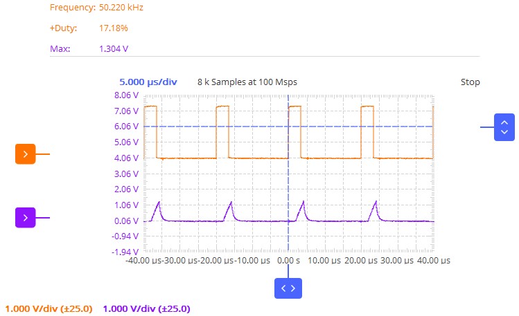
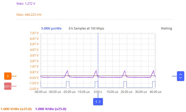
- Click Run->Run menu to compile and load the program to the MCU. We should get a similar waveform on the oscilloscope below. The orange waveform is the PWM applied to the driver IC while the blue waveform is the current feedback.
- Transfer the probe from C10_23 to J16. J16 is the negative input reference of the built-in comparator of the driver IC. Add another probe to C10_12. C10_12 is the comparator output. We should get a similar waveform below. The orange waveform is now the current reference that limits the current to rise above it. The blue waveform is the comparator output. There is some delay on the turn off of the PWM but at least we have some degree on the control of the current limit.
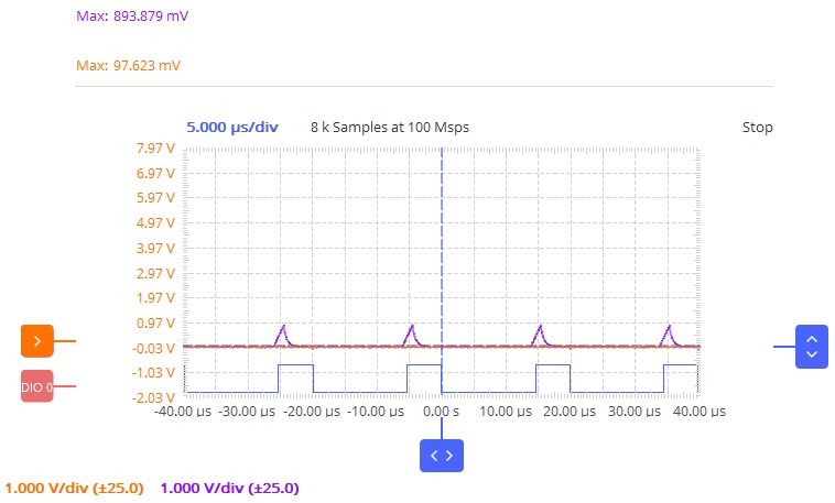
- Next, we set the current limit from 1A from 0A in the code to confirm that we can control the current limit. In line 36, change the code to #define CURRENT_IREF_LIMIT 0. Caution: Setting this value too high may turn the IC too hot.
- Click Run->Run again in the menu to compile and load the program to the MCU. After loading the program, notice that the current reference is now 0V and the peak voltage of the current feedback is reduced to 893.879mV. We can now confirm that we have a cycle-by-cycle control of the Stator PWM.
Comments