How to implement a discrete integrator in LTSPICE

If you are in a hurry and want to immediately verify its function, download and unzipped the file below then run the TestBench.asc file in LTSPICE:
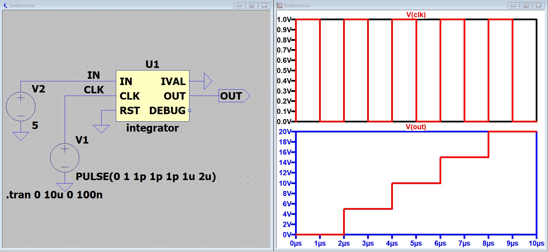
Below left is the schematic on the TestBench.asc file and below right side should be the result of the simulation.
How to use the integrator in another LTSPICE schematic file:
- Copy the integrator.net and integrator.asy files to the folder where your LTSPICE schematic is saved.
- In the LTSPICE schematic window, press F2 to display the "Select Component Symbol" dialog box.
- In the "Select Component Symbol" dialog box. 1st, select the folder where your LTSPICE schematic is saved. 2nd, select the "integrator" from the list then click the OK button.
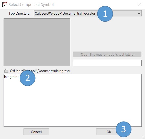
Select Component Symbol - Lastly, click anywhere in the schematic to place the integrator component.
Pin Definition
| PIN NAME | TYPE | DEFINITION |
| IN | Input | The voltage value at this pin is rounded to the nearest integer and then added to the voltage of the OUT pin during positive transition of the CLK pin. |
| CLK | Input | Integration is executed during positive transition of the voltage on this pin. HIGH>0.5V. LOW<0.5V |
| RST | Input | The OUT pin is set to the rounded value of the voltage at the IVAL pin when RST pin is HIGH. HIGH>0.5V. LOW<0.5V |
| IVAL | Input | The voltage value at this pin is rounded to the nearest integer and then transferred to the OUT pin when RST pin is HIGH. |
| OUT | Output | This pin outputs the integrated value. |
| DEBUG | Output | Reserved for debugging the integrator. |
Introduction
There are times that I need to simulate and analyze how a close loop system reacts if a digital PID control is used. A PID has an integrator component with an output that stores a value that can be increased or decreased by its input. My software options are Proteus VSM, PSIM C Block and LTSPICE. In Proteus VSM, I have tried coding a PID in Microchip MPLAB then upload the compiled hex file to a PIC controller in the schematic. In PSIM, I have tried using C Block and have pleasure in the quick result of the simulation. In LTSPICE, the components I know that can store a value are capacitor, inductor and lastly the "sample" component with a data and a clock input. I have utilized the "sample" component since I want a discrete integrator in LTSPICE .
Contents of the integrator.asc file :
.SUBCKT integrator IN CLK RST IVAL OUT DEBUG
;andrew mosqueda
;andrewgs7311@gmail.com
.param bits=12 signed=1
.param maxv=2**(bits-signed)-1
.param minv=-signed*maxv
A1 A1_IN 0 CLK_ 0 0 0 a2_in 0 SAMPLEHOLD vhigh=maxv vlow=minv
A2 a2_in 0 CLK 0 0 0 A2_OUT 0 SAMPLEHOLD vhigh=maxv vlow=minv
A3 CLK 0 0 0 0 CLK_ 0 0 BUF vhigh=1 vlow=0
B1 A1_IN 0 V=if(v(rst), round(v(ival)), round(v(IN))+round(v(A2_OUT)))
B3 OUT 0 V=v(a2_out)
.ENDS
The above ascii file was generated from the schematic below:
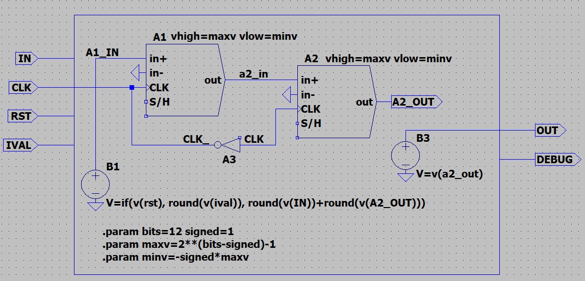
In the above schematic, I have utilized the "sample" components A1 and A2 as storage for the integration. A node (or net) inside the ascii file can be renamed to DEBUG if you want to see the waveform of that node in your simulation.
In the succeeding article, I will discuss on using this discrete integrator in a buck PWM LTSPICE circuit then compare the result to the actual digital implementation of buck PWM converter.
Comments