This is a tutorial on how to monitor the variables of a dsPIC33CH program in real time specifically on the DM330028 dsPIC33CH Curiosity Development Board using UART and switch Interrupt in MPLAB and MCC. The UART and switch Interrupts will be added to a previous MPLAB project (Buck Converter) for simplicity of the explanation.
Procedure
Run MPLAB X IDE.
Close if there are other open projects and files.
Open the buck converter master and slave project.
MASTER CORE CONFIGURATION
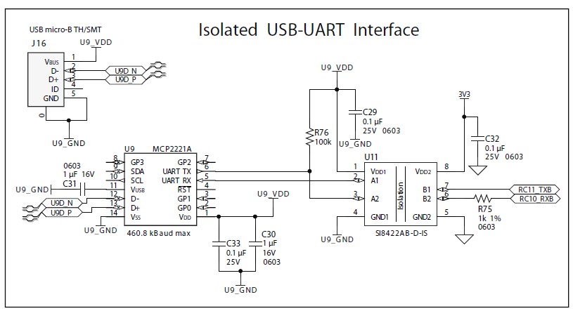
Below is the UART circuit of the DM330028 dsPIC33CH Curiosity Development Board. The circuit is connected to the dsPIC33CH IC by the RC11_TXB and RC10_RXB. Since the buck operation is running in the slave core, RC11 and RC10 pins should be defined as owned by the slave core.
If the master project is not bold highlighted, right click on the master project and select set as Main Project.
Click the MCC button. Wait until MCC is finished loading.
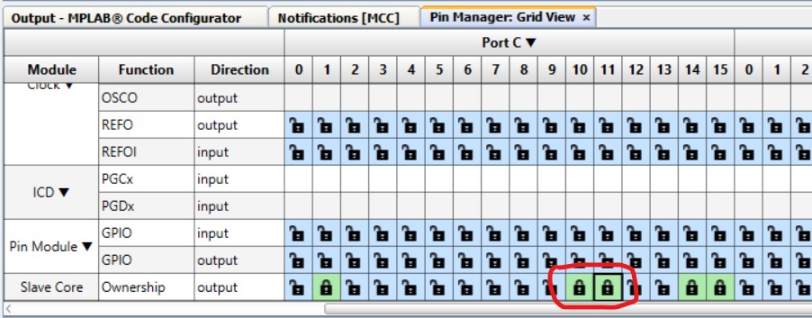
In the Pin Manager Pane, set RC10 and RC11 as owned by slave.
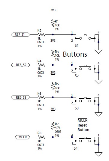
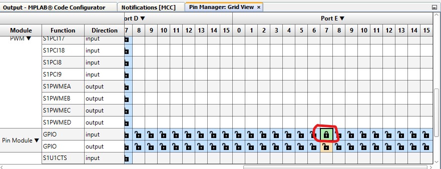
Below is the switches circuit of the DM330028 dsPIC33CH Curiosity Development Board. For this debugging, an interrupt function which contains the UART data transmission will run once everytime switch S1 is pressed. Switch S1 is connected to the dsPIC33CH IC through RE7_S1 pin. Since the buck operation is running in the slave core, RE7 pin should be defined as owned by the slave core.
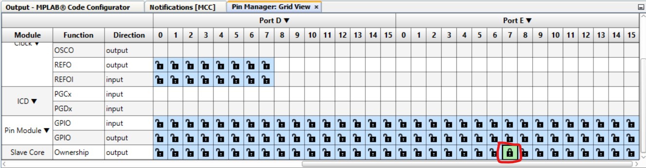
In the Pin Manager of the master project MCC, Set RE7 as owned by Slave Core.
In the Project Resources Pane, click on the Slave Core (don't click x) to open the Slave Core pane.
Click Save Master Settings button. This will update the master_config.mc3 file that will be uploaded later on the Slave project.
In the Project Resources Pane, click Generate button to update the master core configuration files.
Click the MCC button to close the master core configuration.
SLAVE CORE CONFIGURATION
In the Projects tab, if the slave project is not bold highlighted, right click on the slave project and select set as Main Project.
Click the MCC button to open the slave core configuration. Wait until the MCC finished loading.
In the Master Core Pane, click Load Slave Settings from Master Configuration button. Locate and open the master_config.mc3 that was updated in the master core configuration.
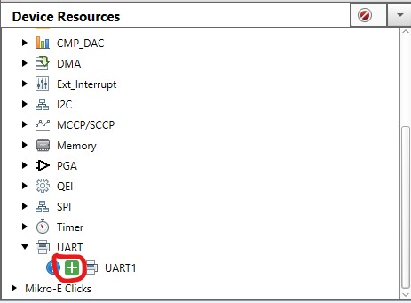
In the Device Resources pane, click + of the UART1 to add UART to the Project Resources pane.
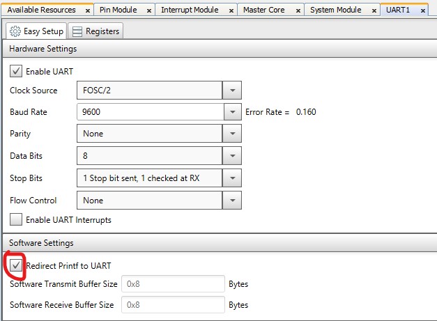
In the UART1 pane, tick the Redirect Printf to UART.
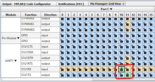
In the Pin Manager Pane, set RC10 pin for S1U1RX of UART1 and RC11 for S1U1TX.
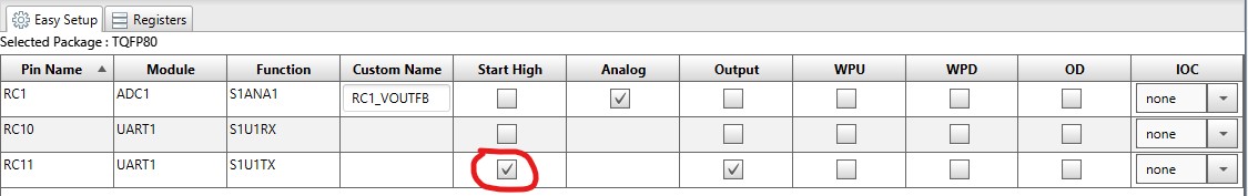
In the Pin Module Pane, tick Start High box for RC11. This is to ensure correct Start bit condition.
Go back to the Pin Manager pane, set RE7 as GPIO input.
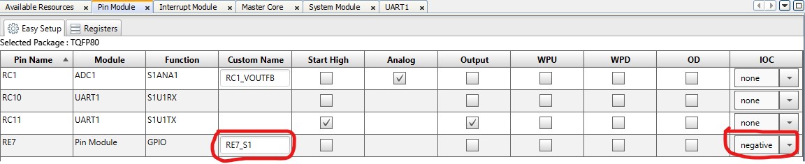
Go back to the Pin Module pane. Rename the RE7 Custom Name to RE7_S1 and change the IOC (Interrupt on Change) to negative.
In the Project Resources pane, click Generate button to update the Slave Core configuration. Click Yes to confirm.
Click the MCC button to close the slave core configuration.
SOURCE CODE
Open the main.c file of the slave project.
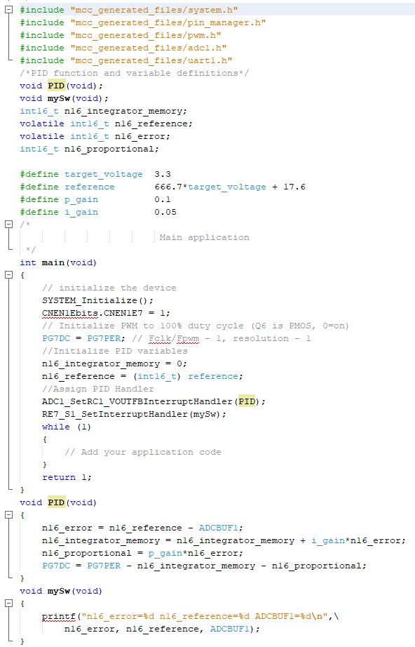
Append the following after the #include "mcc_generated_files/adc1.h" line: #include "mcc_generated_files/uart1.h"
Append the following after the void PID(void); line: void mySw(void); This is the declaration of the new program routine that will send UART data every time the switch on RE7 pin is pressed.
I will monitor the reference, actual and error variables in this exercise. Modify the lines int16_t n16_reference; and int16_t n16_error; to: volatile int16_t n16_reference; volatile int16_t n16_error; Adding volatile before the declaration of a variable is a must if that variable is to be accessed by different program routines.
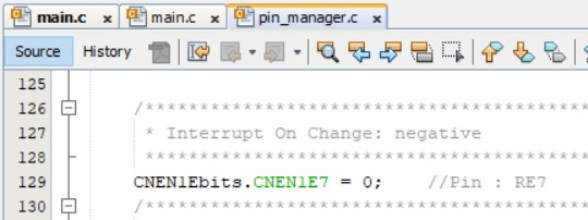
Open the pin_manager.c file of the slave project and check if the Interrupt on Change: negative is 0 (MCC bug) as shown below. If it is 0, then append the following code after the SYSTEM_Initialize(); line in the main.c file: CNEN1Ebits.CNEN1E7 = 1; I don't know why MCC sometimes does not configure this correctly even if the IOC settings in MCC (SLAVE CORE CONFIGURATION step 9) is configured correctly.
Append the following after the ADC1_SetRC1_VOUTFBInterruptHandler(PID); line: RE7_S1_SetInterruptHandler(mySw);
Append the following after the void PID(void) program routine: void mySw(void) { printf("n16_error=%d n16_reference=%d ADCBUF1=%d\n",\ n16_error, n16_reference, ADCBUF1); }
The modified code should now look like below:
RESULT
Make sure J13 (VFB Gain) of the DM330028 dsPIC33CH Curiosity Development Board is shorted.
Connect J20 of the Board to the PC.
Set the master project as the main project.
Click the program buttonon the MPLAB toolbar.
Connect J16 of the DM330028 dsPIC33CH Curiosity Development Board to the PC. This connection will be used for UART communication.
Run a terminal emulator program and connect to the UART. I use the CoolTerm program.
After pressing RE7 thrice, I got the result as shown below.


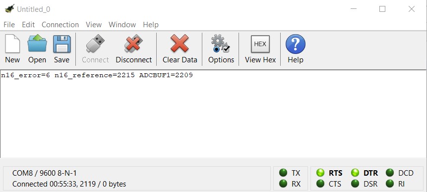
Comments